
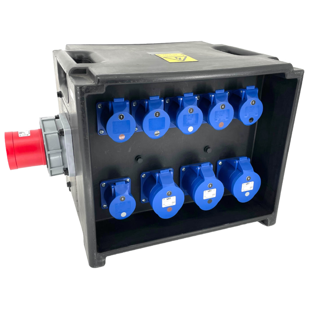
Balancing Asymmetric Loads on a European 230V Single-Phase and 400V Three-Phase Distribution Board
Ever walked up to a commercial distribution board, opened the panel cover, and felt that subtle, low-frequency hum radiating right through your boots? If you have been turning screwdrivers and clamping meters as long as I have, you know that sound immediately. It is the signature cry of an unhappy electrical system. Most of the time, the culprit is pretty straightforward: balancing asymmetric loads on a European 230V single-phase and 400V three-phase distribution board was completely ignored during the last retrofit.
Look, it happens all the time. An electrician pops in to add a few high-power EV chargers or a heavy-duty commercial kitchen appliance, clamps everything onto Phase 1 because it was the easiest busbar to reach, and walks away. Meanwhile, Phase 2 and Phase 3 are practically coasting while Phase 1 is glowing hotter than a summer afternoon in Southern Europe. It is lazy, it is dangerous, and frankly, it costs building owners a fortune in wasted energy and premature equipment failure.
In standard European low-voltage networks, we rely heavily on a 400V three-phase four-wire Wye (TN-S or TN-C-S) configuration. You get 400V line-to-line for your big industrial motors and 230V line-to-neutral for standard plug loads and lighting. But when those 230V single-phase loads pull vastly different currents across L1, L2, and L3, the neutral wire stops being a quiet return path and turns into a highway for excessive current. Honestly? It is one of the most underdiagnosed issues in modern facility management.
Achieving proper phase load balancing is not just about keeping inspectors happy. It is about preventing voltage drops, stopping unnecessary breaker trips, and protecting expensive equipment from negative phase sequence currents. Let us roll up our sleeves and dive into how to fix unbalanced load distribution in low-voltage panelboards without losing your sanity.
The Mechanics of Voltage Imbalance in European Panelboards
Understanding the 230V/400V Wye System Setup
To fix the issue, you have to respect how European power distribution works at the local board level. The transformer secondary gives us three phase conductors spaced 120 electrical degrees apart, alongside a central neutral point connected to earth. When every phase pulls identical current at identical power factors, the vector sum of those currents at the neutral point equals zero. Perfect harmony. Beautiful, right?
Real life is rarely that clean. In any real-world installation, your distribution panel feeds dozens of single-phase office computers, heat pumps, coffee machines, and server racks. These individual loads cycle on and off unpredictably throughout the workday. When L1 pulls 80 Amps, L2 pulls 40 Amps, and L3 pulls 15 Amps, your neat vector triangle collapses into a chaotic mess.
This variance creates phase current unbalance, which directly causes line-to-neutral voltages to shift. The heavily loaded phase experiences a voltage dip due to excessive $I^2R$ line losses, while the lightly loaded phases can actually see their voltage rise above nominal levels. That is how sensitive electronic gear on Phase 3 ends up getting cooked because Phase 1 was over-leveraged.
Seriously, voltage shift is no joke. Even a minor 2% to 3% voltage unbalance on a three-phase system forces three-phase induction motors to run significantly hotter, dropping their operating efficiency like a stone and shortening their lifespan drastically.
Why Neutral Currents Creep Up on You
Here is where things get really uncomfortable for facility engineers. In a perfectly balanced three-phase system, the neutral conductor carries virtually no current. Because of this, older electrical codes sometimes allowed engineers to install downsized neutral conductors in main feeders. That was a massive design mistake given modern non-linear electrical loads.
When you encounter asymmetric three-phase loading, the vector sum of the fundamental phase currents no longer cancels out. The residual current has nowhere to go except straight down the neutral conductor back to the supply transformer. If your neutral wire is carrying 60 Amps continuously on a board rated for 100 Amps per phase, that wire is cooking inside the conduit.
Combine neutral current magnitude issues with modern non-linear loads like variable frequency drives (VFDs) or LED driver banks, and the problem doubles down. Third-harmonic currents (150 Hz in Europe) add in-phase along the neutral line rather than cancelling out, compounding the heat created by your basic load imbalance.
I have seen main distribution panels where the neutral busbar was literally discolored from extreme thermal stress while the individual phase breakers were operating well below their thermal trip ratings. If that does not make you double-check your clamp meter readings, nothing will.
Practical Strategies for Equalizing Phase Distribution
Mapping Circuits with Clamp Meters and Power Quality Analyzers
You cannot balance what you do not measure. Step one in fixing an unequal phase load distribution is putting away the guesswork and bringing out high-end diagnostic tools. Grab a True-RMS clamp meter with logging capabilities, or better yet, lock a portable power quality analyzer onto the incoming mains of the distribution board for a full 7-day monitoring cycle.
Why a full week? Because facility load profiles change drastically depending on operational schedules. A snapshot reading at 10:00 AM on a Tuesday will not tell you what happens when the building HVAC pumps ramp up on a hot Thursday afternoon or when office equipment goes standby over the weekend. You need continuous, time-stamped RMS current and voltage data across all three phases.
During your audit, log both the instantaneous currents and the total active ($kW$) and reactive ($kVAR$) power per phase. Pay close attention to peak load overlapping. A circuit pulling 16 Amps for five minutes twice a day requires a completely different load-allocation strategy than a server rack drawing a constant 16 Amps 24 hours a day, 7 days a week.
Once you have gathered raw data, calculate the voltage unbalance factor (VUF) using the standard European (IEC) formula. If your VUF exceeds 1% to 2%, it is time to intervene. Anything above 3% requires immediate remedial action before critical equipment suffers permanent insulation breakdown.
Strategic Rotation of High-Draw Single-Phase Loads
Once your load data is clear, the real physical labor begins: physical phase rotation within the panelboard. The primary goal of electrical panel load balancing is redistributing single-phase branch circuits so that the total kVA demand is spread as evenly as humanly possible across L1, L2, and L3.
Start by identifying your largest 230V single-phase consumers. We are talking about modern high-draw appliances: split-system air conditioners, heavy kitchen equipment, single-phase EV chargers, and large UPS systems. These single-phase "load hogs" should never be bunched together on the same phase busbar just because the wiring layout was convenient for the installer.
Follow a structured step-by-step approach when rearranging your board connections:
- Safely isolate the distribution board following proper lockout/tagout (LOTO) safety protocols.
- Group all single-phase branch circuits by operational characteristics (e.g., continuous baseline loads vs. intermittent high-peak loads).
- Move dedicated high-draw single-phase breakers across the three busbar phases to equalize expected peak currents.
- Ensure lighting and general socket circuits are split evenly down the chassis busbars instead of landing sequentially on L1.
- Re-energize the panel board and take real-time current readings under full load conditions to confirm proper balance.
It sounds simple on paper, but in practice, you must double-check wire lengths and panel clear spaces before unmounting breakers. Short neutral tails can make re-routing a real headache if the original panel wiring was cut tight to the board margins.
Mitigation Techniques and Advanced Hardware Solutions
Deploying Dynamic Load Balancing Systems
Manual circuit rotation works absolute wonders for static, predictable building loads. But what happens when you introduce dozens of electric vehicles charging at variable rates throughout the day? Traditional static balancing completely falls apart under those dynamic conditions. That is where active hardware steps into the light.
Modern dynamic load balancing hardware uses smart energy management modules paired with motorized transfer switches or smart EV chargers. These controllers monitor incoming main busbar currents via current transformers (CTs) in real time. If Phase 1 begins to overload while Phase 2 has spare capacity, the smart system dynamically throttle down single-phase chargers on Phase 1 or switches controllable loads to underutilized phases.
For large-scale commercial facilities, installing an Active Power Filter (APF) or an Active Load Balancer directly at the main 400V switchboard is the ultimate technical solution. These power electronic devices inject compensating reactive and active currents into the supply lines in real time, instantly neutralizing phase imbalance and absorbing harmonic distortions on the fly.
Yes, dynamic hardware adds upfront equipment costs. But when you factor in saved transformer capacity, lower line losses, and avoiding utility penalty fees for phase asymmetry, the return on investment often lands comfortably under two to three years.
Managing Harmonics and Neutral Line Overheating
You cannot talk about reducing neutral current in 400V systems without addressing total harmonic distortion (THD). As I mentioned earlier, high harmonic loads will mess up your neutral conductor balance even if your 50Hz fundamental current looks perfectly balanced on paper across all three phases.
To combat harmonic-driven neutral heating, ensure your distribution boards are specified with double-capacity neutral busbars (rated for 200% of the phase current capacity) whenever high densities of IT gear or non-linear loads are installed. It gives your system the thermal headroom needed to handle triplen harmonics safely.
Here is a list of effective technical interventions to combat phase imbalance and neutral overheating simultaneously:
- Install Zig-Zag (Phase-Shifting) grounding transformers to absorb zero-sequence and triplen harmonic currents locally before they hit the main supply lines.
- Deploy dedicated single-phase isolated circuits for sensitive audio/visual or laboratory instrumentation to isolate them from noisy commercial power lines.
- Upgrade standard circuit protection to four-pole circuit breakers (4P MCBs/MCCBs) on main feeders, ensuring neutral isolation and protection under severe fault conditions.
- Incorporate passive or active harmonic filters directly at the supply terminals of major non-linear three-phase loads.
Combining mechanical phase matching with effective harmonic filtering converts an unstable, hot-running distribution network into a cool, rock-solid power system that runs smoothly for decades.
Common Questions About Balancing Asymmetric Loads
What is the maximum acceptable phase imbalance on a 400V three-phase panel?
Under standard European guidelines (such as EN 50160), line voltage unbalance should generally be kept under 2% for normal operating conditions. From a current perspective, a good engineering target is keeping phase current variation within 10% of the average line current across all three phases.
How does an unbalanced load affect my electricity bill?
Unbalanced loads increase your total $I^2R$ power losses in both the phase conductors and the neutral wire, which shows up as pure wasted energy on your meter. Additionally, industrial grid operators often charge heavy financial penalty surcharges if your site exhibits poor power factor or significant phase current asymmetry at the point of common coupling.
Can I just double the size of the neutral conductor to solve imbalance issues?
Upsizing the neutral wire prevents the conductor from overheating and burning off insulation due to excessive unbalance or triplen harmonic currents. However, it does not fix the underlying voltage drop, phase angle shifts, or efficiency losses inside connected three-phase motors. Upsizing the neutral is a thermal safety measure, not a complete solution for load imbalance.