
How to Step Up AC Voltage Using Single-Phase Step-Up Transformers: Sizing and Winding Ratios
Ever tried running a heavy-duty power tool only to realize your wall outlet just doesn't deliver enough juice? It's frustrating. You click the switch, hear a sad hum, and watch your equipment stall out. I've been there, standing in a workshop surrounded by expensive machinery that was essentially useless because the utility grid handed me 120V when I desperately needed 240V.
That is precisely where learning how to step up AC voltage using single-phase step-up transformers saves the day. These sturdy blocks of iron and copper are the unsung heroes of electrical distribution, quietly converting low voltage into high voltage without moving a single mechanical part. But before you go slapping wires together, you need to understand what makes these machines tick. It's not just magic; it's pure magnetism and math.
Getting it right requires a firm grasp on two non-negotiable concepts: transformer sizing and the precise calculation of winding ratios. If you mess up the math, best-case scenario, your equipment won't run. Worst-case scenario? You get a very expensive fireworks show and a room full of acrid smoke. Let's make sure that doesn't happen.
Look—stepping up voltage isn't reserved for utility engineers with advanced degrees. With a solid understanding of fundamental electromagnetic principles, you can safely specify, calculate, and implement a single-phase step-up transformer for almost any application. Let's dive deep into how this all works.
Demystifying Transformer Winding Ratios and Voltage Multiplication
The Magnetic Core and Faraday's Law
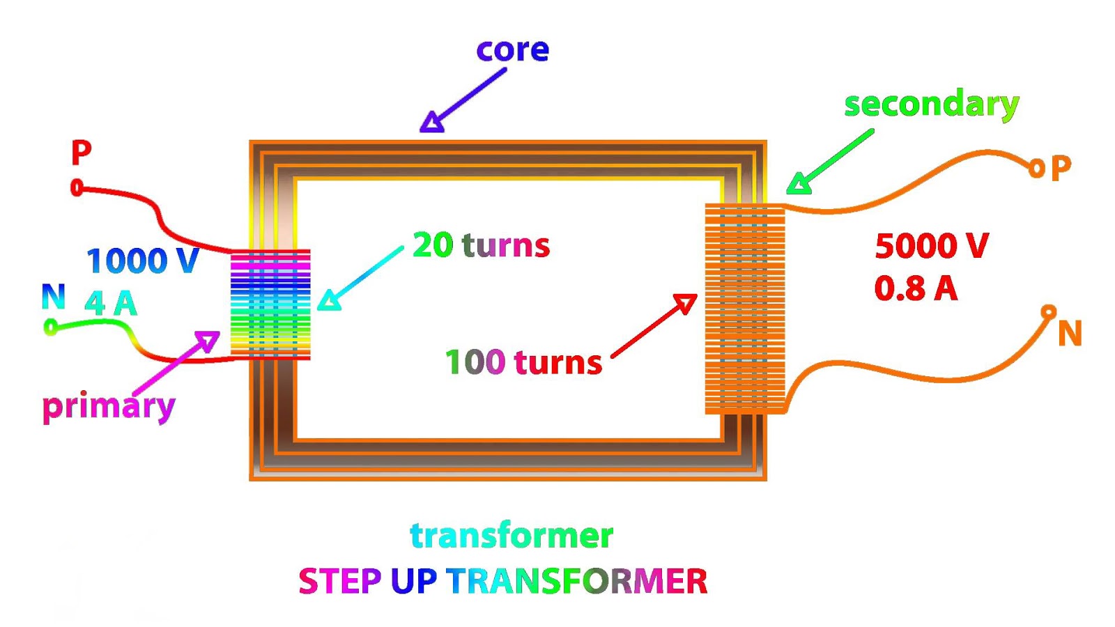
At its heart, a single-phase transformer relies on mutual induction. You have two separate coils of insulated wire wrapped around a shared magnetic core made of laminated silicon steel. The coil connected to your input power source is the primary winding, while the coil feeding your load is the secondary winding. When alternating current flows through the primary side, it creates a continuously collapsing and expanding magnetic flux within the core.
This shifting magnetic field passes right through the secondary coil, inducing an alternating voltage across its terminals. This process follows Faraday's Law of Electromagnetic Induction. Because the core efficiently channels magnetic flux, almost all the energy transfers from the primary side to the secondary side with minimal losses. It's simple, elegant, and extraordinarily reliable.
In a step-up transformer design, the goal is simple: yield a higher output voltage than the input voltage. To achieve this, the secondary winding must contain more loops of wire than the primary winding. Every single loop of wire in the secondary coil cuts through the shared magnetic flux, picking up a tiny increment of induced voltage. Add more loops, get more voltage.
Honestly? It's amazing how a simple shift in loop count transforms electrical potential. If you double the loops on the output side, you double the voltage. It really is that straightforward on a conceptual level, though high-frequency parasitics and core saturation add real-world spice to the mix.
Calculating the Turns Ratio with Precision
To master how to step up AC voltage using single-phase step-up transformers, you must master the turns ratio formula. The relationship between input voltage (Vp), output voltage (Vs), primary turns (Np), and secondary turns (Ns) is strictly proportional. We express this with a straightforward mathematical equation: Vs / Vp = Ns / Np. The ratio of secondary turns to primary turns directly dictates your voltage step-up factor.
Let's walk through a real-world scenario. Suppose you have a standard 120V AC input, but your industrial load requires 480V AC. Divide 480 by 120, and you get a voltage ratio of 4:1. This means your step-up transformer turns ratio must be exactly 1 to 4. For every single turn of wire on the primary coil, you need four turns on the secondary coil.
If your primary winding has 200 turns of wire, your secondary winding must feature 800 turns. Simple arithmetic, right? But remember, real-world transformers aren't 100% efficient due to winding resistance and core losses. You often need to add a slight percentage boost—around 2% to 5% extra turns on the secondary side—to compensate for full-load voltage drops.
Keep in mind that while voltage goes up, total power remains constant (minus minor thermal losses). Conservation of energy dictates that power in equals power out (Pin = Pout). Therefore, as voltage increases on the secondary side, current must decrease proportionally. A step-up transformer increases voltage, but it steps down current.
Current Inversion and Wire Gauge Considerations
Because current behaves inversely to voltage, the primary side of a single-phase step-up transformer draws significantly more current than the secondary side delivers. This fundamental rule directly dictates how you build or select your transformer windings. Higher current requires thicker wire to prevent overheating, while lower current allows for thinner wire.
If you step up 120V at 40 Amps to 480V, the secondary side will only draw 10 Amps (120V 40A = 4800VA, and 480V 10A = 4800VA). Consequently, your primary winding must be wound using heavy-gauge wire, like 8 AWG or 6 AWG, to carry that heavy 40-Amp continuous input load without melting the insulation.
Conversely, the secondary winding carries only 10 Amps, meaning you can safely use a thinner gauge wire, such as 14 AWG. Ignoring this current inversion is a rookie mistake. Using wire that is too thin on the high-current primary side generates massive I²R copper losses, turning your custom transformer into a glorified space heater.
Always double-check your thermal ratings. Insulation degradation caused by excessive current heat is the leading cause of transformer failure worldwide. Match your conductor's cross-sectional area to the actual amperage each specific winding carries.
Accurate Sizing and KVA Calculations for Single-Phase Load Requirements
Determining Voltage, Amperage, and Power Requirements
Proper transformer sizing is the difference between a smooth-running system and tripping breakers every ten minutes. You cannot simply guess the rating you need based on the physical size of an old unit. You must carefully sum up the total volt-amperage (VA) or kilovolt-amperage (kVA) requirements of your connected loads.
Start by auditing every piece of electrical equipment connected to the secondary side. Note the operating voltage (V) and the full-load current (I) listed on the equipment nameplates. For simple resistive loads like heaters or incandescent lights, calculated apparent power in VA is simply voltage multiplied by current (VA = V * I).
However, when dealing with reactive loads like electric motors, solenoids, or modern switching power supplies, power factor (PF) enters the picture. Motors draw both real power (watts) and reactive power (VARs). You must size your single-phase step-up transformer based on total apparent power (VA), not just active watts, to handle the total current flowing through the windings.
Seriously, never size a transformer using only wattage specs. Doing so completely ignores magnetic magnetizing current, leading to severe thermal overload even when your wattmeter says everything should be fine.
Calculating Required kVA Capacity
Once you have your total load VA, convert it to kilovolt-amperes by dividing by 1,000. For single-phase systems, the fundamental sizing equation is remarkably simple: kVA = (Volts Amps) / 1000. If your stepped-up 240V output needs to feed a continuous 30-Amp industrial load, your minimum power requirement is (240 30) / 1000 = 7.2 kVA.
Standard transformers come in pre-determined commercial sizes, such as 0.5 kVA, 1 kVA, 3 kVA, 5 kVA, 7.5 kVA, 10 kVA, 15 kVA, and 25 kVA. In our 7.2 kVA example, buying a 7.5 kVA transformer seems logical at first glance. But operating right at the absolute limit leaves zero room for error, ambient heat fluctuations, or future expansion.
Engineers consistently apply a safety buffer. Standard industry best practice dictates adding a minimum 25% margin above your maximum anticipated load. Multiplying 7.2 kVA by 1.25 yields 9.0 kVA. Therefore, you should select a standard 10 kVA single-phase step-up transformer to ensure longevity and cool operation.
This 25% safety margin protects your investment against environmental stress, grid voltage fluctuations, and unexpected load shifts. Running a transformer cool dramatically extends the lifespan of its internal paper and resin insulation systems.
Factoring in Inrush Current and Motor Starting Loads
Inductive loads, particularly electric motors, present a massive challenge during startup. When an electric motor starts from a dead stop, it exhibits low initial impedance, causing an instantaneous surge known as locked-rotor amperage or inrush current. This initial spike can easily reach 5 to 8 times the motor's rated full-load current.
If your single-phase step-up transformer is sized strictly for running current, that massive startup surge causes a sharp momentary voltage dip (sag). Severe sags prevent the motor from reaching full operational speed, cause control relays to chatter, or trigger thermal magnetic circuit breakers.
To safely step up AC voltage for motor loads, check the NEMA code letter on the motor nameplate. This code defines locked-rotor kVA per horsepower. If you run a 3 HP motor, your running load might only be 3.5 kVA, but startup demand could briefly spike to 15 kVA or higher.
To prevent voltage sag issues, either size up the unit significantly or utilize a specialized transformer rated for heavy motor-starting duty. Adding a soft-starter or variable frequency drive (VFD) downstream can also tame high inrush currents, allowing for a more economical transformer size.
Step-by-Step Implementation and Wiring Practices
Selecting Core Geometry and Winding Materials
When selecting or constructing a single-phase step-up transformer, physical construction plays a vital role in operational efficiency. Core construction generally falls into two categories: shell-type and core-type geometries. Shell-type cores surround the windings with magnetic steel, offering superior flux containment and higher efficiency, making them popular for custom stepping applications.
Winding material is another crucial selection choice. Copper offers excellent electrical conductivity, low thermal expansion, and higher mechanical strength against short-circuit forces. Aluminum, while lighter and cheaper, features higher electrical resistance and requires larger wire cross-sections to carry identical currents.
Pay close attention to core saturation limits. If you attempt to step up voltage using a core that is physically too small, the magnetic flux density will exceed the core's saturation point (measured in Teslas). Saturation drops inductive reactance, causing primary current to surge uncontrollably and overheat the transformer.
Always verify that the core cross-sectional area matches your operating frequency (typically 50Hz or 60Hz) and target power levels. Lower frequencies require larger cores to avoid saturation, which is why a 50Hz transformer is physically larger than a 60Hz unit of identical kVA rating.
Wiring Schematics, Taps, and Grounding Protocols
Proper wiring is vital when installing a step-up configuration. High-quality single-phase transformers often feature dual-voltage primary and secondary windings (e.g., 120/240V primaries and 240/480V secondaries). These multi-tap configurations feature multiple lead wires (labeled H1, H2, H3, H4 for high voltage, and X1, X2, X3, X4 for low voltage).
To configure a multi-winding unit as a step-up transformer, you connect the lower-voltage supply to the low-voltage (X) terminals and draw higher voltage from the high-voltage (H) terminals. Connecting windings in parallel increases current capacity while keeping voltage low; connecting windings in series increases voltage rating.
Safety grounding requires careful attention. The secondary side of a step-up transformer creates a separately derived electrical system. You must establish a solid ground bond on the secondary neutral terminal (if applicable) and connect the transformer steel enclosure directly to your main building grounding electrode conductor.
Never leave a step-up secondary floating unless your specific application specifically requires an ungrounded system monitored by insulation detectors. Floating secondaries present severe shock hazards, as stray capacitive coupling can cause elevated voltages relative to ground.
Testing, Commissioning, and Diagnostics
Before energizing your high-voltage output, perform strict cold checks. Use a digital multimeter or megohmmeter (Megger) to check insulation resistance between the primary winding, secondary winding, and ground frame. Insulation resistance should comfortably exceed several megohms; low readings indicate moisture contamination or physical insulation damage.
Next, check winding resistance using a low-resistance ohm meter. The primary winding should read noticeably lower resistance than the high-voltage secondary winding due to thicker wire and fewer turns. If your low-voltage side shows higher resistance than the high-voltage side, stop immediately—you've likely misidentified your primary and secondary leads.
Perform an initial no-load power test. Connect your input source while keeping all secondary loads disconnected. Measure the open-circuit output voltage to verify your actual step-up transformer turns ratio matches design calculations. Check for excessive vibration, humming, or rapid core heating.
Finally, apply your electrical load incrementally while monitoring primary and secondary currents using a calibrated clamp meter. Confirm that output voltage remains stable within acceptable operating limits (typically +/- 3% to 5% of rated voltage) under full-load conditions.
Common Questions About How to Step Up AC Voltage Using Single-Phase Step-Up Transformers
Can I use a standard step-down transformer in reverse to step up voltage?
Yes, standard single-phase transformers are bi-directional devices. You can feed power into the low-voltage secondary side to obtain higher voltage on the primary side. However, because factory step-down units include extra secondary turns to compensate for load voltage drop, running them in reverse yields slightly lower output voltage than expected. To correct this, choose a unit with adjustable primary taps.
What happens if I connect a step-up transformer to a DC power source?
Connecting a step-up transformer directly to a Direct Current (DC) source will destroy it. Transformers require changing magnetic flux driven by Alternating Current (AC) to induce secondary voltage. With steady DC, inductive reactance drops to zero, turning the primary coil into a direct short circuit. This causes massive overcurrent, tripped breakers, and burned wire insulation within seconds.
How do I choose between an autotransformer and an isolated step-up transformer?
Autotransformers share a single continuous winding between input and output, making them smaller, cheaper, and more efficient for modest voltage changes (e.g., stepping 200V up to 240V). However, they provide zero electrical isolation. If your application demands complete galvanic isolation between primary and secondary circuits for safety or noise suppression, choose a dual-winding isolated step-up transformer instead.
Why does output voltage drop significantly when I turn on my load?
A dramatic drop in secondary voltage under load indicates severe voltage regulation issues. Common causes include an undersized transformer kVA capacity, excessively long or thin input wiring causing primary voltage drops, or drawing heavy reactive currents with a low power factor. Calculate your total inrush and running current to ensure your transformer and supply circuits are correctly sized.