
Wind Tunnel Modeling & Thermal Bridging: Why Façade Engineering Computational Work Is Harder Than Typical Structural Frame Analysis
Ever tried explaining to a client why their shiny new tower needs another six weeks of envelope analysis when the main structural frame was signed off in a weekend? I have. More times than I care to admit. The client usually looks at me like I just claimed gravity works differently on the twentieth floor. But here is the raw truth from the trenches: standard building frame design is mostly a solved game, while structural envelope physics is a chaotic, non-linear nightmare.
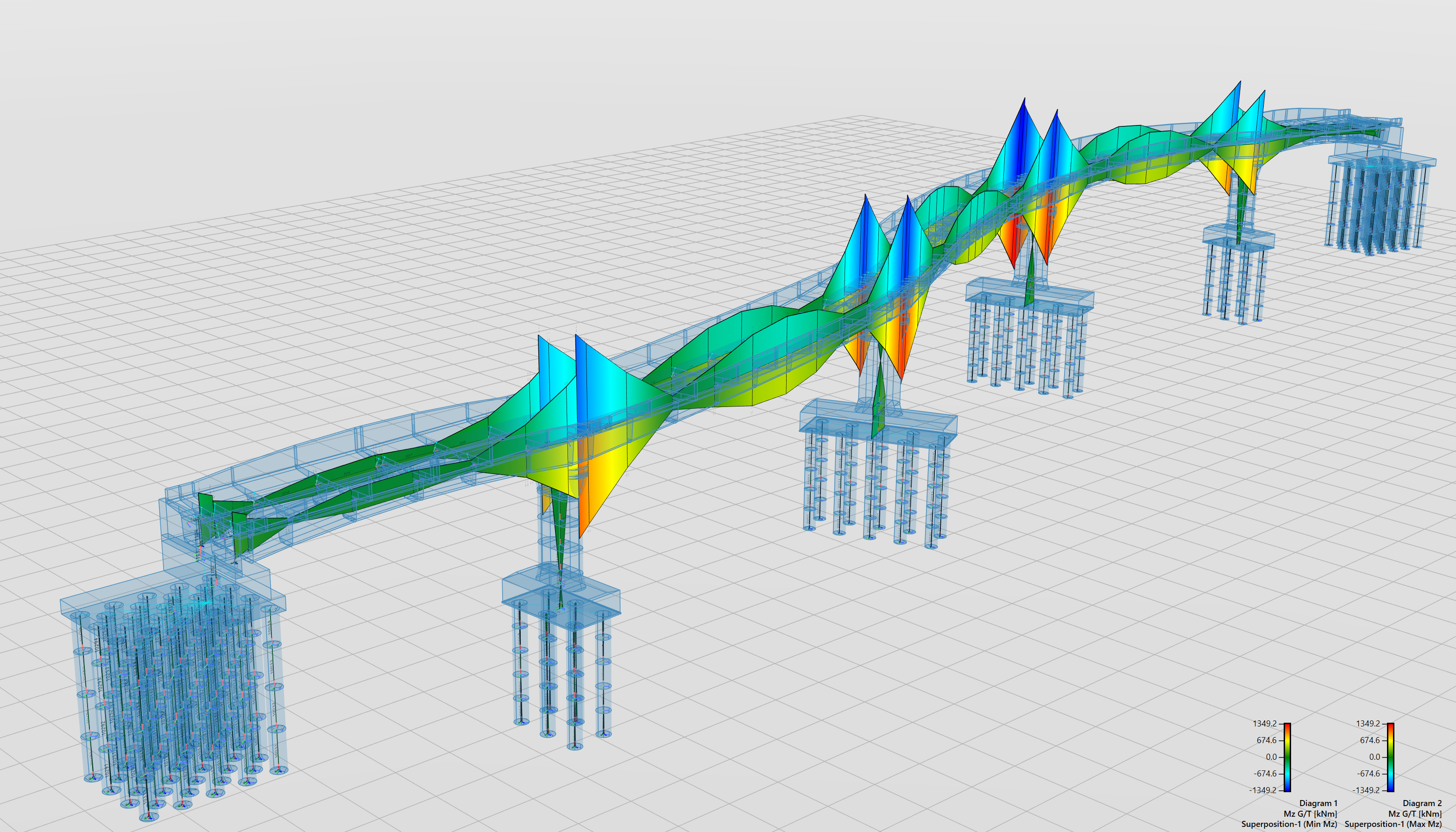
When you run a standard column-and-beam system, you are dealing with well-behaved, predictable materials obeying tidy formulas. Steel yields when it is supposed to. Concrete cracks where you expect it to. You build a stick model, throw on some load combinations, and let the solver churn out your moment diagrams. Easy, right?
The exterior skin is an entirely different beast.
When we dive into wind tunnel modeling and thermal bridging, we stop working with neat geometry and linear elastic equations. We are suddenly forced to model turbulent fluid dynamics, micro-climate pressure spikes, three-dimensional heat transfer through complex assemblies, and material interactions that change based on the weather. Façade engineering structural frame comparison studies consistently show that envelope analysis requires far more computational horsepower and engineering intuition than the main skeleton ever will.
The Chaos of Wind Tunnel Modeling versus Linear Structural Frames
Why Fluid Dynamics Makes Structural Engineers Cry
Look, main frame analysis relies heavily on static or equivalent static wind loads provided by building codes. You grab a pressure coefficient from a table, apply it to a surface area, and call it a day. But actual wind does not give a damn about your static code tables. Real wind swirling around a modern skyscraper is turbulent, chaotic, and wildly unpredictable.
Computational Fluid Dynamics (CFD) and physical wind tunnel modeling attempt to capture this madness. Unlike solid structural elements where stress travels down clear load paths, fluid particles interact with every single architectural fin, corner recess, and balcony slab. A minor change in a mullion profile can create localized vortex shedding that doubles the local peak pressure on a glass panel two floors down. That level of sensitivity simply does not exist in standard grid frame modeling.
To accurately model wind-induced envelope loads, we have to solve the Navier-Stokes equations across millions of mesh cells. We are not just checking if a beam bends; we are tracking transient pressure fluctuations over time. A single transient wind simulation can take days to solve, whereas a full 3D frame linear analysis finishes before your coffee gets cold.
Honestly? Fluid dynamics is where predictable geometry goes to die.
Corner Effects and Dynamic Peak Pressures
The main structural core cares about base shear and overturning moments—global numbers that average out across the entire footprint. Façade engineering structural frame comparison highlights a massive divergence here. The exterior envelope does not get the luxury of global averaging. It feels every localized pressure spike directly on its skin.
Take negative pressure zones at building corners. As wind hits a sharp structure edge, it separates and creates powerful suction vortices. These localized suction loads can easily be double or triple the positive pressures calculated for the center of the wall. If your wind tunnel modeling misses these micro-phenomena, you risk blowing glass panels straight off the building during a moderate storm.
Mapping these hyper-local dynamic pressure fields back onto flexible skin components requires immense computational overhead. You cannot just use a uniform distributed load. You must map complex, time-dependent spatial pressure grids onto non-linear finite element models of glass and aluminum. It is tedious, precise, and utterly unforgiving.
Fluid-Structure Interaction: When the Envelope Fights Back
Here is where things get truly wild: Fluid-Structure Interaction (FSI). In traditional frame design, the structure deforms so slightly under wind that the wind flow itself does not change. We call that a uncoupled problem. You calculate the wind load, apply it to the rigid building, and walk away.
Flexible building skins, tensile membranes, and double-skin facades do not play by those rules. As high-velocity wind pushes against a large glass panel or flexible shading blade, the component deforms. That physical deformation changes the shape of the aerodynamic surface, which instantly alters the airflow pattern, which changes the dynamic load again.
Simulating FSI requires two-way coupled solvers running simultaneously. The CFD solver updates the aerodynamic forces, passes them to the non-linear structural solver, which calculates the shape change, and feeds the new geometry back into the CFD solver for the next millisecond of time-step. It is a computational nightmare that makes typical frame analysis look like high school algebra.
Thermal Bridging and Complex Multi-Physics Simulations
Three-Dimensional Heat Flow Is Never Simple
If you think structural loads are tough, welcome to the world of envelope thermodynamics. Standard structural design ignores temperature for the most part, treating it as a simple uniform strain expansion coefficient ($\Delta T$). But when analyzing the exterior skin, heat flow is a multi-dimensional, non-linear physical process that ruins your sleep schedule.
Thermal bridging occurs wherever a highly conductive material—like aluminum framing, steel brackets, or concrete slab edges—breaks through the continuous insulation layer. You cannot accurately evaluate these junctions using simple 1D or 2D calculations. Heat does not just flow straight outward; it leaks sideways, around corners, and through fasteners in complex 3D paths.
Modeling these thermal junctions requires full 3D finite element heat transfer simulations. You have to account for conduction through solid metals, convection within internal air cavities, and radiative heat exchange between internal surfaces. Skip one of these heat transfer modes, and your performance prediction is useless.
It is a relentless balance between structural capacity and thermal efficiency.
Condensation Risks, Isotherms, and Dew Point Traps
Why do we care so much about micro-level thermal bridging? Because mistreating thermodynamics leads to moisture, mold, and structural failure. When a thermal bridge cools an interior surface below the dew point of ambient indoor air, moisture condenses on metal brackets or inside hidden wall cavities.
To prevent this, engineers plot thermal isotherms through ultra-detailed cross-sections of window walls and curtain wall mullions. We must verify that the critical $13^\circ\text{C}$ or $15^\circ\text{C}$ temperature line stays well outside the internal sealants and structural attachment points under extreme winter conditions.
Consider what happens when you combine structural loading with thermal movement. A curtain wall bracket must support heavy dead loads of triple-pane glass while simultaneously minimizing metallic cross-sectional area to stop heat loss. Shrinking the bracket optimizes thermal performance, but it raises structural stresses to the absolute limit. Balancing structural integrity against thermodynamic isolation requires continuous iterative optimization.
Non-Linear Material Combinations in Modern Assemblies
A primary steel frame consists of... well, steel. A concrete frame consists of concrete and rebar. Their material properties are standardized, isotropic, and well-documented. A unitized curtain wall assembly, however, is a chaotic sandwich of wildly different materials shoved into a three-inch envelope.
In a single joint, you might have:
- Extruded aluminum alloys (high thermal expansion, non-linear plastic behavior)
- Structural silicone sealants (hyperelastic, non-linear viscoelastic behavior)
- Laminated architectural glass (brittle, viscoelastic interlayer materials like PVB or SentryGlas)
- EPDM rubber gaskets (compressible, highly non-linear elastomer)
- Polyamide thermal break strips (composite plastic with temperature-dependent properties)
Simulating how this mess behaves under combined wind pressure, differential thermal expansion, and seismic inter-story drift requires complex hyperelastic and viscoelastic material constitutive models. You are not just solving $F = kx$; you are solving highly non-linear differential equations where stiffness changes continuously with strain rate, temperature, and time.
Comparing Computational Requirements: Envelope versus Primary Structure
Parameter Primary Structural Frame Analysis Façade Engineering Computational Work Dominant Physics Linear Elasticity, Static/Dynamic Structural Mechanics Multi-Physics (CFD, Non-Linear Mechanics, 3D Heat Transfer) Material Behavior Isotropic, Linear Elastic (Yield limits defined by code) Hyperelastic, Viscoelastic, Anisotropic, Temperature-Dependent Geometry Scale Macro-scale (10m to 100m members, coarse stick models) Micro-scale to Macro-scale (0.5mm sealant joints to 100m towers) Loading Inputs Simplified code-based static equivalents Transient dynamic CFD wind fields, solar radiation, thermal gradients Mesh Complexity Low to Moderate (Thousands of beam/shell elements) Extremely High (Millions of 3D solid and fluid domain cells) Multi-Scale Geometry Problems
The core reason façade engineering structural frame comparison favors envelope complexity comes down to geometric scale ratios. In main frame modeling, your smallest element might be a one-meter beam section, and your largest is a three-hundred-meter tower. That is a scale ratio of $1:300$.
In exterior skin engineering, we must analyze the entire 300-meter tower height to capture global wind pressure variations, but we also have to model the 1-millimeter structural silicone adhesive joint that prevents the glass panel from detaching. That is a geometric scale ratio of $1:300,000$.
Computer finite element solvers hate multi-scale geometry. To bridge the gap from a sub-millimeter sealant bead to a macro-scale building face without generating billions of impossible elements, engineers must use complex sub-modeling techniques. You run a global macro-model to extract displacements and forces, then feed those boundary conditions into a micro-model of the localized joint. It doubles or triples the analytical workload.
Iterative Design Loops vs Linear Workflows
Frame design generally moves in a linear direction. Structural engineers determine the grid, size the primary members based on gravity and lateral drift, and pass those reaction forces down to the foundation engineers. Sure, there are revisions, but the analytical path is clear.
Skin engineering is locked in endless iterative feedback loops across multiple disciplines:
- The architect wants ultra-clear, highly transparent, non-reflective glass facades.
- The building physics engineer demands high-performance low-E coatings and thick insulation to meet energy codes, which darkens the glass.
- The structural engineer increases glass thickness to handle dynamic pressure spikes from wind tunnel modeling.
- The extra glass weight increases dead load deflection, requiring larger aluminum mullions.
- Larger aluminum mullions create massive structural thermal bridging paths, failing energy compliance.
- The thermal engineer adds larger polyamide thermal breaks, reducing the structural shear capacity of the aluminum frame.
- Return to Step 1 and repeat until everyone is exhausted.
Every small adjustment in geometry or material specification requires re-running non-linear structural, thermal, and daylighting simulations simultaneously. It is an exhausting exercise in continuous trade-offs.
Common Questions About Façade Engineering & Analysis
Why can't standard structural engineers design building envelopes?
Standard structural training focuses heavily on linear elasticity, concrete design, steel frame stability, and global lateral force resistance. Envelope engineering requires specialized expertise in non-linear multi-physics, fluid dynamics, hyperelastic materials, building science thermodynamics, and glass mechanics. It is a completely different engineering discipline.
Is CFD wind modeling accurate enough to replace physical wind tunnels?
Not entirely. While Computational Fluid Dynamics (CFD) has advanced dramatically, physical wind tunnel modeling using scale models in boundary-layer wind tunnels remains the gold standard for high-rise buildings. CFD is fantastic for early schematic exploration, but physical testing is still required by structural codes for complex tall towers to capture exact dynamic vortex shedding and micro-peak suction forces accurately.
How does thermal bridging affect structural integrity over time?
Uncontrolled thermal breaks allow interstitial condensation to form inside sealed wall assemblies. Over time, this trapped moisture corrodes structural steel brackets, degrades anchor bolts, rots internal insulation, and causes structural silicone sealants to lose adhesion. Thermal failures almost always turn into structural degradation failures given enough time.
What software tools are used for facade engineering analysis?
Façade specialists rely on specialized multi-physics suites rather than basic frame solvers. Popular software includes THERM and WINDOW (for 2D heat transfer), ANSYS or ABAQUS (for 3D non-linear FEA, structural silicone, and glass stress analysis), OpenFOAM or ANSYS Fluent (for CFD wind simulations), and Strand7 or RFEM (for specialized plate and glass element modeling).
Designing the structural skeleton of a skyscraper is a monumental task, no doubt about it. But when you look at the sheer density of physics compressed into the outer two inches of a building, it is easy to see why envelope analysis is the most complex computational challenge in modern architectural design.